
One-Stop Cold Storage Solutions: Design, Manufacture & Support
One-Stop Cold Storage Solutions: Design, Manufacture & Support
Category: Condensing Units
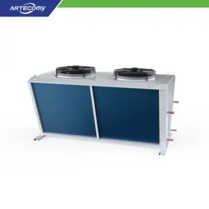
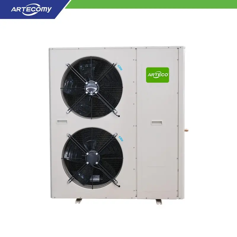
The Air Cooled Box Condenser Φ630 is a dual-fan heat rejection unit engineered for freezer-grade refrigeration systems. Two Φ630mm axial fans draw ambient air across a copper-tube, aluminum-fin coil to reject 25–35 kW of heat, making this condenser a dependable partner for condensing units serving -25°C to -40°C cold rooms, freezer warehouses and food freezing lines. Its box-type construction integrates the coil, fans and mounting frame into one rigid package that installs quickly on rooftops, exterior walls or ground-level condenser yards.
This condenser is specified wherever freezer systems need reliable outdoor heat rejection. Common installations include frozen food storage rooms at -18°C to -25°C, low-temperature distribution warehouses, seafood and meat freezing operations, ice plants and process chillers using HFC refrigerants. It fits both new construction and retrofit projects replacing aging condensers, since the box footprint and connection positions accommodate typical replacement scenarios. For sites with high ambient temperatures, the dual-fan layout maintains condensing pressure control during summer peaks, protecting compressor efficiency and product temperature stability.
Fin spacing determines how the coil behaves over years of operation, not just on delivery day. The 2.5mm spacing packs more fin surface into the same face area, which raises heat transfer and can reduce coil size for a given duty – an advantage in clean-air environments with scheduled coil cleaning. The 3.0mm spacing leaves wider air passages that resist clogging from dust, pollen, cottonwood seed or salt-laden coastal air, and cleans more easily when fouling occurs. Our engineers recommend the spacing based on your site’s air quality, maintenance program and design ambient temperature so the condenser holds its rated performance throughout its service life rather than only at commissioning.
Every coil is assembled with mechanically expanded copper tubes, pressure-tested to refrigerant service standards and leak-checked before the fans and frame are fitted. Fan assemblies are balanced and run-tested, and each finished unit receives a final inspection against the build specification. Arteco coordinates condenser selection with compressor capacity, refrigerant charge and line sizing so the delivered package performs as a matched system. Installation guidance covers airflow clearances, vibration isolation and drainage for defrost or washdown water.
The condenser must reject the compressor’s cooling capacity plus its heat of compression at the project’s design ambient temperature. For a matched selection, send us the compressor model, refrigerant, evaporation temperature and site ambient; our engineers will confirm the correct coil and fan configuration.
Yes, with the correct options. We recommend the wider 3.0mm fin spacing, and enhanced surface protection can be specified for salt-air exposure. Share your site conditions in the RFQ so the unit is built for them.
Yes. The coil and circuit design are compatible with R449A as well as R507A and R404A, supporting projects that must meet newer refrigerant regulations while keeping proven HFC service practices.
Keep the coil faces clean and unobstructed, inspect fan blades and guards periodically, and verify electrical connections during seasonal checks. Most capacity loss in air-cooled condensers comes from fouled coils, so a simple cleaning schedule preserves efficiency.
Condenser performance is set as much by location as by manufacture. The unit needs clear airflow on all sides – recirculation of hot discharge air back into the coil face is the most common cause of high condensing pressure in the field. We specify clearances during layout and orient the air discharge away from prevailing wind and adjacent equipment. Mounting decisions follow the site: rooftop placement suits most facilities, wall mounting serves space-constrained plants, and ground installation simplifies maintenance access. Noise propagation to occupied areas and property boundaries is reviewed where relevant. Refrigerant line routing between compressor and condenser is sized for acceptable pressure drop and oil return. Planning these factors at design stage keeps the condenser rejecting at rated capacity throughout its life.
Clearances depend on unit size and installation configuration; we specify them in the layout drawings for each project so airflow remains unrestricted and service access is preserved.
| Specification | Value |
|---|---|
| Fan Diameter | Φ630mm |
| Fan Count | 2 Fans |
| Motor Power | 0.55kW × 2 |
| Heat Rejection | 25-35 kW |
| Compatible Refrigerants | R507A, R449A, R404A |
| Tube Material | Copper with Aluminum Fins |
| Fin Spacing | 2.5mm / 3.0mm |
| Application | Freezer Systems |